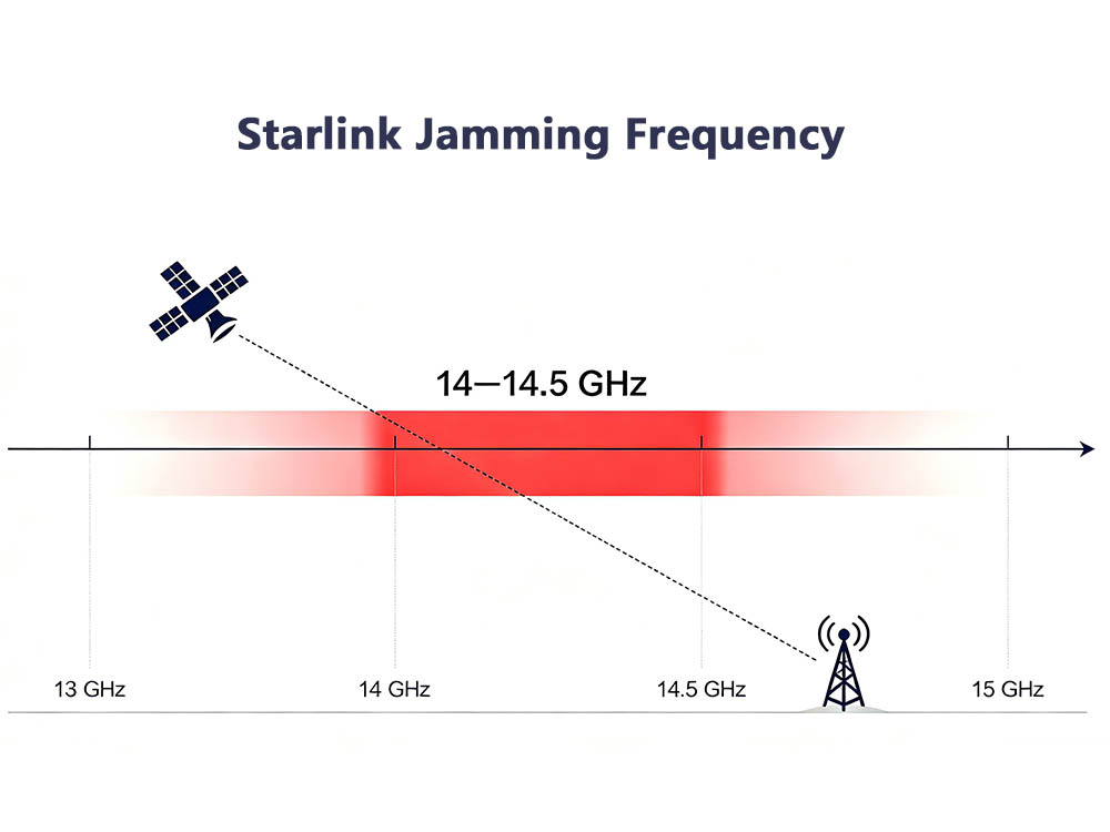
Why 14-14.5 GHz is the primary Starlink jamming frequency comes down to RF planning, not marketing. Starlink user terminals transmit to the constellation in the 14.0–14.5 GHz Ku-band uplink. Any effective jammer that targets the terminal-to-satellite return path must therefore prioritize this slice of spectrum.
Why 14-14.5 GHz Is the Primary Starlink Jamming Frequency
Starlink’s user link uses two Ku-band windows: 10.7–12.7 GHz for downlink and 14.0–14.5 GHz for uplink. The uplink is the weaker, more exposed path. A user terminal has limited EIRP and a small aperture, while the satellite receiver must listen across a wide coverage area. A ground-based interferer that raises noise in 14-14.5 GHz can reduce the signal-to-noise ratio before the satellite demodulates the terminal’s burst.
This is why Ku-band uplink planning matters. Downlink jamming at 10.7–12.7 GHz must flood a much larger user receive footprint. Uplink jamming at 14-14.5 GHz can be aimed at the satellite’s receive beam and exploit the same geometry as the legitimate terminal.
Ku-Band Uplink Physics
At 14 GHz, a compact horn or phased array still delivers useful gain. Rain fade is higher than at L-band, but Starlink links are designed with margin and adaptive coding. A jammer module can use solid-state power amplifiers, band-pass filters, and directional antennas to concentrate energy in 14.0–14.5 GHz. The goal is not to destroy hardware; it is to degrade the uplink enough that packets fail.
ITU Radio Regulations allocate 14.0–14.5 GHz to Fixed-Satellite Service uplinks in many regions. That allocation is precisely why Starlink uses it, and why interference here affects the service’s return link. The FCC and other regulators treat unauthorized jamming as illegal interference.
Jammer Module Design at 14-14.5 GHz
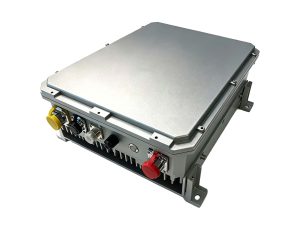
A practical 14-14.5 GHz jammer module usually includes:
-
A stable local oscillator or SDR source.
-
A 14.0–14.5 GHz band-pass filter.
-
A high-gain power amplifier with thermal control.
-
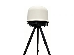
A directional antenna or phased array.
-
Power and timing control to avoid self-interference.
These blocks are not exotic, but they must handle higher atmospheric loss and tighter mechanical tolerances than lower-band systems.
Comparison Table
| Link | Frequency | Direction | Jamming Relevance |
|---|---|---|---|
| User uplink | 14.0–14.5 GHz | Terminal → satellite | Primary Starlink jamming frequency; attacks satellite receiver |
| User downlink | 10.7–12.7 GHz | Satellite → terminal | Wider area needed; harder to blanket |
| Gateway feeder | 17.8–18.6 GHz / 10.7–12.7 GHz | Gateway ↔ satellite | Different geometry; not terminal-level primary |
Regulatory and Operational Risks
Jamming 14-14.5 GHz is not a victimless test. It can disrupt emergency communications, violate national spectrum laws, and trigger geolocation. Starlink and its parent SpaceX can use spectrum monitoring and satellite telemetry to identify uplink interference. Penalties can include fines, equipment seizure, and criminal charges.
Countermeasures and Outlook
Operators can mitigate uplink interference with spot-beam nulling, power control, frequency agility, and stricter authentication. Yet the fundamental physics remains: 14-14.5 GHz is where the user terminal talks back. That makes it the first band to watch, test, and protect.
In short, why 14-14.5 GHz is the primary Starlink jamming frequency is simple: it is the uplink. If the return link fails, the user experience fails with it. Any serious jammer module, spectrum monitor, or counter-UAS plan for Starlink must start at 14.0–14.5 GHz.