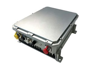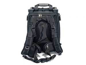
Starlink jamming system maintenance and field support is not a secondary logistics task. It is the difference between a denial capability that lasts a full operation and one that becomes dead weight after two weeks. Yet most procurement documents focus on jamming range and frequency coverage, ignoring how the system will behave under dust, heat, and repeated transport. This article outlines five critical steps drawn from field reports and contractor debriefs.
1. Realistic Maintenance Cycles
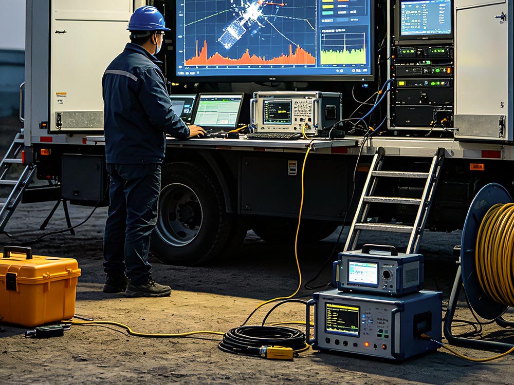
Manufacturer datasheets assume clean power, stable temperatures, and trained operators. Field conditions break those assumptions quickly. A vehicle-mounted Starlink jamming system operating in 45°C ambient heat may need filter cleaning every 72 hours, not every 500 hours. For effective Starlink jamming system maintenance and field support, reset your maintenance clock based on environmental sensors, not calendar days. Track amplifier temperature, fan speed, and input voltage. When any of these drift beyond 10% of baseline, schedule preventive work immediately.
2. Common Field Failure Modes
Three failures dominate field returns: power amplifier overheat, cable connector corrosion, and software lockup after frequency hopping. The first is mechanical; the second is environmental; the third is firmware-related. A structured maintenance log helps identify patterns. If the same amplifier fails twice in one month, the problem is not the amplifier. It is the cooling path. Starlink jamming system maintenance and field support must treat repeat failures as system design clues, not isolated part replacements.
3. Spare Parts and Tool Kits
Do not send a system into the field without a minimum spares package. The table below shows recommended quantities for a 90-day deployment.
| Spare Item | Quantity per System | Estimated Lead Time | Priority |
|---|---|---|---|
| RF amplifier module | 1 | 4–6 weeks | Critical |
| Directional coupler | 1 | 2–3 weeks | High |
| Fan assembly | 2 | 1 week | High |
| Cable connector kit | 3 sets | 1 week | Medium |
| Control board | 1 | 6–8 weeks | Medium |
Stocking these parts before deployment prevents a 45-day downtime for a $300 connector. This is a core principle of Starlink jamming system maintenance and field support.
4. Operator-Level Diagnostics
Not every fault needs an engineer. Train operators to run built-in self-tests, read power supply status, and swap modular RF cards.
Quick Diagnostic Steps for Starlink Jamming System Maintenance and Field Support
A simple fault tree printed on laminated cards can reduce field service calls by 40%. Include steps for checking VSWR, verifying PLL lock, and resetting the control interface. The faster the operator isolates the failure, the sooner the system returns to mission. This is a low-cost but high-impact part of Starlink jamming system maintenance and field support.
5. Contractor vs. Organic Support
Small units often rely on vendor field service engineers. That works until the vendor refuses travel into a contested area. Build organic capability for the top five failure modes. A two-person team with a multimeter, torque wrench, and spare fan can handle most Starlink jamming system maintenance and field support tasks without external help. Reserve contractor support for calibration and complex RF alignment.
Finally, document everything. After each mission, log operating hours, ambient temperature, and any fault codes. This data predicts failures before they happen. For more on jamming techniques, see our internal guide to Starlink uplink jamming methods and anti-Starlink system cost factors. External resources from IEEE Xplore and Janes provide deeper reliability data for military RF systems.