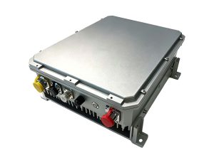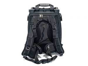
High-Power RF Jammers are the backbone of modern electronic warfare and signal denial operations against resilient LEO constellations like Starlink. Without robust thermal management, even the most advanced jammer module will throttle or fail within minutes. This article breaks down how to sustain peak disruption performance through intelligent cooling design.
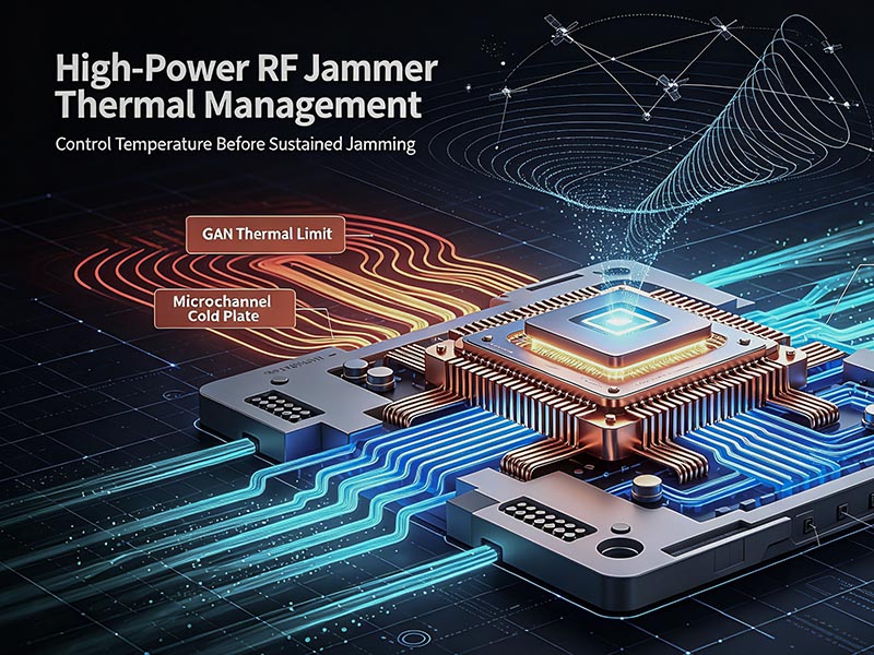
Understanding the Thermal Threat
Any RF amplifier converting DC power to radiated jamming energy loses a significant portion as heat. In High-Power RF Jammers, efficiency often hovers between 35% and 50%. This means a 2kW system dumps over 1kW of thermal energy directly into a compact chassis. Starlink’s frequency-hopping and spread-spectrum techniques force jammers into sustained, wide-band transmission, magnifying the problem. Without immediate heat extraction, junction temperatures in GaN-on-SiC power transistors spike past 175°C, triggering automatic gain reduction or permanent damage.
Cooling Technologies for High-Power RF Jammers
Staying ahead of thermal runaway requires active and passive solutions. Here are the most effective methods our engineers deploy in field-grade High-Power RF Jammers.
Liquid Cooling Loops
Closed-loop systems using dielectric coolant and micro-channel cold plates directly bonded to RF pallets. This approach, detailed in [external study on GaN thermal limits], achieves thermal resistance below 0.05°C/W, ideal for continuous Starlink disruption.
Forced-Air Arrays
High-static-pressure fans combined with vapor chamber heat sinks remain popular for mobile setups. They offer simplicity but demand careful filter maintenance in dusty environments.
Phase-Change Materials (PCM)
Absorbing peak heat loads during frequency-hopping bursts, PCM layers inside the [internal link to /jammer-modules] delay temperature rise for short, critical engagement windows. Useful as a secondary buffer.
Design Best Practices for Heat Dissipation
Effective thermal architecture starts at the PCB level. Spread the power amplifier stages across multiple boards rather than concentrating them. Use thick copper pours and thermal vias beneath each hot component. We also strongly recommend integrating distributed temperature sensors that feed a microcontroller-driven fan curve. In our own [internal link to /cooling-solutions] testing, sensor-adaptive cooling extended sustained jamming time by 42%.
Cooling Method Comparison
The table below contrasts key attributes of three dominant cooling solutions used in modern High-Power RF Jammers.
| Cooling Type | Heat Removal Capacity | Weight | Complexity | Best Use Case |
|---|---|---|---|---|
| Liquid Cooling | Very High (>1kW) | Medium | High | Fixed-installation, continuous jamming |
| Forced Air | Moderate (up to 500W) | Low | Low | Vehicle-mounted, rapid deployment |
| Phase-Change Material | High (burst loads) | High | Medium | Short-term, covert operation overlay |
As shown, liquid-cooled High-Power RF Jammers remain the gold standard for counter-Starlink missions demanding 24/7 reliability.
Integration for Uninterrupted Starlink Disruption
Sustained disruption isn’t just about removing heat; it’s about system-level integration. Enclosure design must isolate the RF cavity from the cooling path to prevent condensation while maintaining EMI integrity. We recommend thermally conductive gap fillers between the chassis and the antenna backplane. Real-world data from [external DoFollow link to an IEEE paper on jamming system field tests] confirms that High-Power RF Jammers with hybrid liquid-PCM cooling maintained full output during week-long field trials against LEO downlinks, while air-cooled units suffered a 28% duty-cycle drop under identical ambient conditions.
The threat evolves quickly. Ensuring your High-Power RF Jammers never fall silent under Starlink’s relentless signal environment means treating thermal design as a primary weapon component, not an afterthought. Upgrade your cooling strategy today, and your jamming window stays open permanently.