A Ku-band jammer is a specialized electronic warfare device designed to disrupt communication signals within the Ku-band frequency range (12–18 GHz). This portion of the electromagnetic spectrum is widely used for satellite television, military radar, and broadband internet. By flooding a receiver with noise or deceptive signals, a Ku-band jammer can effectively block legitimate data transmission.
Understanding how this technology functions requires a look at both the physics of radio interference and the hardware involved. Below, we break down the fundamentals.
What Is a Ku-Band Jammer?
A Ku-band jammer targets the specific frequencies used by geostationary satellites and terrestrial microwave links. Its primary purpose is to deny an adversary the ability to communicate or gather intelligence. Because Ku-band signals are highly directional and susceptible to weather attenuation, a well-tuned jammer can exploit these vulnerabilities with relatively low power.
How a Ku-Band Jammer Works
The principle is straightforward: transmit a stronger signal on the same frequency as the target. The receiver gets overwhelmed and cannot distinguish the original data. Modern jammers use techniques such as sweep jamming, barrage jamming, and spot jamming. Each method has trade-offs, as shown in the table below.
| Jamming Technique | Bandwidth Coverage | Effectiveness | Typical Use Case |
|---|---|---|---|
| Spot Jamming | Narrow (single channel) | High power density | Disrupting a specific satellite transponder |
| Sweep Jamming | Wide (sequential) | Moderate | Countering frequency-hopping systems |
| Barrage Jamming | Very wide (simultaneous) | Lower power per channel | Denying an entire Ku-band segment |
| Deceptive Jamming | Matched to signal | High (confuses receiver) | Replaying altered GPS or sync data |
In every case, the Ku-band jammer aims to raise the noise floor above the signal level. Engineers must carefully calculate effective radiated power (ERP) and antenna gain to achieve the desired range. For deeper technical guidelines, refer to external resources like the IEEE Xplore digital library.
Key Components of a Ku-Band Jammer
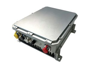
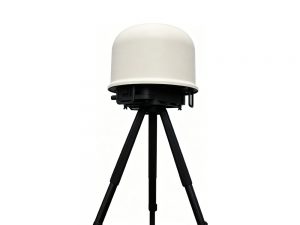
A typical Ku-band jammer consists of four main subsystems:
-
Signal Generator: Creates the interfering waveform (noise, tones, or modulated pulses).
-
Power Amplifier: Boosts the signal to the required wattage, often using GaN or traveling wave tube technology.
-
Antenna System: A parabolic dish or phased array that focuses the jamming energy toward the target satellite.
-
Control Unit: Allows the operator to switch frequencies, modulation schemes, and duty cycles in real time.
These components must work in harmony to produce a stable, powerful output without damaging the jammer’s own electronics.
Real-World Applications
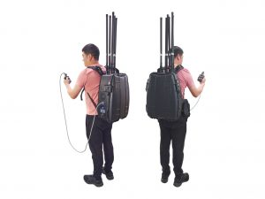
A Ku-band jammer is predominantly used by defense forces to disable enemy drone feeds, block unauthorized satellite broadcasts, or protect convoys from remotely triggered explosives. It also appears in counter-unmanned aerial system (C-UAS) solutions. Law enforcement agencies may deploy jammers during hostage situations to prevent the use of satellite phones.
Legal and Ethical Considerations
Unauthorized use of a Ku-band jammer is illegal in most countries because it can interfere with critical services like aviation navigation and emergency communications. The U.S. Federal Communications Commission (FCC), for example, prohibits the marketing and operation of jamming devices. Authorized military and government applications are the exceptions, strictly regulated to avoid collateral disruption.
As satellite networks expand with low Earth orbit constellations, the need to understand and control a Ku-band jammer becomes even more urgent. Whether for national security or spectrum management, this technology sits at the intersection of physics, engineering, and policy.